Electrical properties of Silicon (Si)

Electrical properties
Basic PropertiesMobility and Hall Effect
Transport Properties in High Electric Field
Impact Ionization
Recombination Parameters
Surface Recombination
Basic Properties
| Breakdown field | ≈3·105V/cm |
| Mobility electrons | ≤1400 cm2 V-1s-1 |
| Mobility holes | ≤450 cm2 V-1s-1 |
| Diffusion coefficient electrons | ≤36 cm2/s |
| Diffusion coefficient holes | ≤12 cm2/s |
| Electron thermal velocity | 2.3·105m/s |
| Hole thermal velocity | 1.65·105m/s |
Mobility and Hall Effect
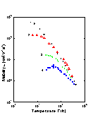 |
Electron mobility versus temperature for different doping levels. 1. High purity Si (Nd< 10-12 cm-3); time-of-flight technique (Canali et al. [1973]) 2. High purity Si (Nd< 4·10-13 cm-3): photo-Hall effect (Norton et al. [1973]) 3. Nd= 1.75·1016 cm-3; Na = 1.48·1015 cm-3; Hall effect (Morin and Maita [1954]). 4. Nd= 1.3·1017 cm-3; Na = 2.2·1015 cm-3; Hall effect (Morin and Maita [1954]). |
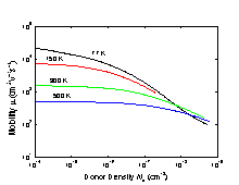 |
Electron drift mobility versus donor density at different temperatures (Li and Thumber [1977]). |
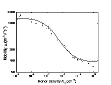 |
Electron drift mobility versus donor density, T=300 K. (Jacoboni et al. [1977]). |
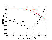 |
The electron Hall factor versus donor density. 77 and 300 K. Solid lines show the results of calculations. Symbols represent experimental data (Kirnas et al. [1974]). |
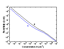 |
Resistivity versus impurity concentration for Si at 300 K. |
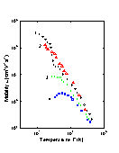 |
Temperature dependences of hole mobility for different doping levels. 1. High purity Si (Na = 1012 cm-3); time-of-flight technique (Ottaviany et al. [1975]); 2. High purity Si (Na~1014 cm-3); Hall-effect (Logan and Peters [1960]) 3. Na=2.4·1016 cm-3; Nd=2.3·1015 cm-3; Hall-effect (Morin and Maita [1954]) 4. Na=2·1017 cm-3; Nd=4.9·1015 cm-3; Hall-effect (Morin and Maita [1954]) |
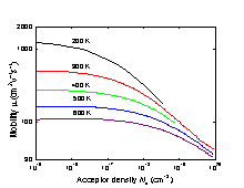 |
Hole drift mobility versus acceptor density at different temperatures (Dorkel and Leturcq [1981]). |
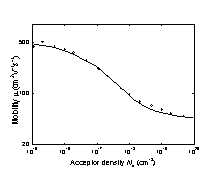 |
Hole drift mobility versus acceptor density. 300 K. (Jacoboni et al. [1977]). |
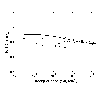 |
The hole Hall factor versus acceptor density. 300 K. (Lin et al. [1981]). |
Transport Properties in High Electric Field
 |
Si. Electron drift velocity vs. electric field. Solid lines: F||(111). Dashed lines: F||(100). Jacoboni et al. (1977). |
 |
Si. Electron drift velocity vs. electric field at different temperatures. F||(111). Jacoboni et al. (1977). |
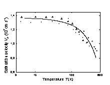 |
Temperature dependence of the saturation electron drift velocity (Jacoboni et al. [1977]). Solid line is calculated according to equation: vs=vso·[1+C·exp(T/Ι)]-1, where vso=2.4·107 cm s-1, C=0.8, Ι=600K. |
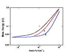 |
Mean energy of electrons as a function of electronic field F at different
donor densities. F||(111). 300 K. 1. Nd = 0; 2. Nd = 4·1018 cm-3; 3. Nd = 4·1019 cm-3. (Jacoboni et al. [1977]). |
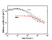 |
The field dependence of longitudinal electron diffusion coefficient
D for 77K and 300 K. F || (111). Dotted and solid lines show the results of Monte-Carlo simulation. Symbols represent measured data. (Canali et al. [1985]). |
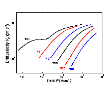 |
Field dependences of the hole drift velocity at different temperatures. F || (100). (Jacoboni et al. [1977]). |
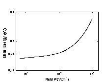 |
Mean energy of holes as a function of electronic field F. Na = 0, T=300 K. (Jacoboni et al. [1977]). |
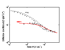 |
The field dependence of longitudinal hole diffusion coefficient D
for 77K and 300 K. F||(111). Dotted and solid lines show the results of Monte-Carlo simulation. Symbols represent measured data. (Canali et al. [1985]). |
Impact Ionization
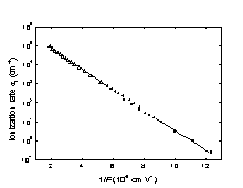 |
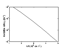
Electron ionization rate αi vs. 1/F. T = 300 K. (Maes et al. [1990]). |
 |
Hole ionization rate βi vs. 1/F. T = 300 K. (Grant [1973]). |
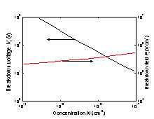 |
Breakdown voltage and breakdown field vs. doping density for an abrupt
p-n junction. T = 300 K. (Sze [1981]). |
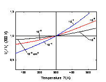 |
Normalized breakdown voltage vs. temperature for an abrupt p-n
junction at different doping levels. (Crowell and Sze [1981]). |
Recombination Parameters
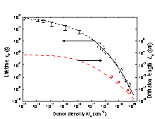 |
Lifetime τp and diffusion length Lp of holes
in n-type Si vs. donor density. T = 300 K. For 1012 cm-3 < Nd ≤ 1017 cm-3- from numerous experimental data for good quality industrial produced n-Si. For Nd ≥ 1017 cm-3 - (Alamo and Swanson [1987]). Lp (Na) dependence (dashed line) is calculated as Lp(Nd)=[Dp(N)·τp(N)]1/2, where Dp=(kB·T/q)·μp. |
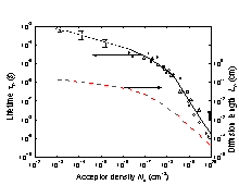 |
Lifetime τn and diffusion length Ln of electrons
in p-type Si vs. acceptor density. T = 300 K. For 1013 cm-3 < Na≤1016 cm-3 - from numerous experimental data for good quality industrial produced p-Si. For Na ≥ 1016 cm-3 - (Tyagi and Van Overstraeten [1983]). Ln(Na) dependence (dashed line) is calculated as Ln(Na)=[Dn(N)·τn(N)]1/2, where Dn=(kb·T/q)·μn. |
Surface recombination
Surface recombination rate depending on treatment of Si surface lies in the range between 102 ÷(6-8)·104cm/s.Surface recombination rate on the Si-SiO2 interface can be as small as ≤ 0.5 cm/s.
| Si | Remarks | Referens | |
| The longest lifetime of holes tp | |||
| Diffusion length Lp = (Dp x tp)1/2 | Surface Recombinaton Velocity | ||
| Radiative recombination coefficient B | 1.1 x 10⁻¹⁴ cm3/s | Gerlach et al. (1972) | |
| Auger coefficient Cn | 1.1 x 10⁻³⁰ cm6/s | 300 K | |
| Auger coefficient Cp | 0.3 x 10⁻³⁰ cm6/s | 300 K | |
| Auger coefficient C = Cn + Cp | 1.4 x 10⁻³⁰ cm6/s | 300 K |